Injection unit of injection molding machine
- Share
- Issue Time
- Jul 29,2020
Summary
As for the injection molding machine, several types such as plunger type, plunger preplasticating type, screw preplasticating type and in-line screw type, etc. have been developed so far, but presently the in-line screw type injection molding machine
1.Injection capacity
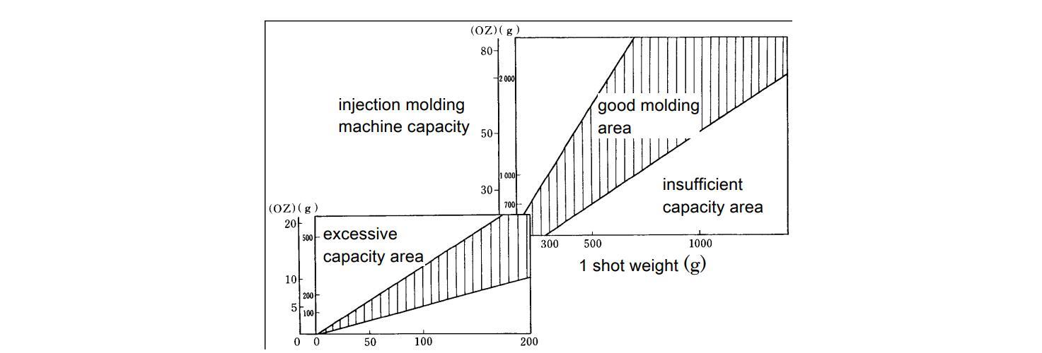
The proper injection capacity is found from the relationship of the molding machine capacity for the weight of 1 shot as shown in Figure 1・1-2. It is necessary to select the molding machine that satisfies the capacity of the shaded area. This figure is the summary of the actual molding results in the past, but basically, it is based on the following idea.
Selection
of
molding
machine
from
the
injection
capacity
At the side where the capacity is small, plasticizing time and injection time become long, and it is used at the narrow capacity of the molding machine. That is, the filling shortage is caused due to the extension of molding cycle and slow filling rate.
On the other hand, at the side where the capacity is large, dwell time of the resin inside the cylinder becomes long, and the resin thermally decomposes. The capacity range in the figure is indicated rather widely, but when it is easy to be thermally decomposed with materials containing lots of pigments and additives, it is better to conduct the molding at shot weight of 70~80% of the injection capacity.
2.Barrel
Generally, using the material (for example, nitride steel etc.) for the molding of Iupilon / NOVAREX is good. However, concerning the molding of glass fiber reinforced grade (Iupilon GS etc.) and optical grade (Iupilon H-400 etc.), it is good to consider the following for the barrel material.
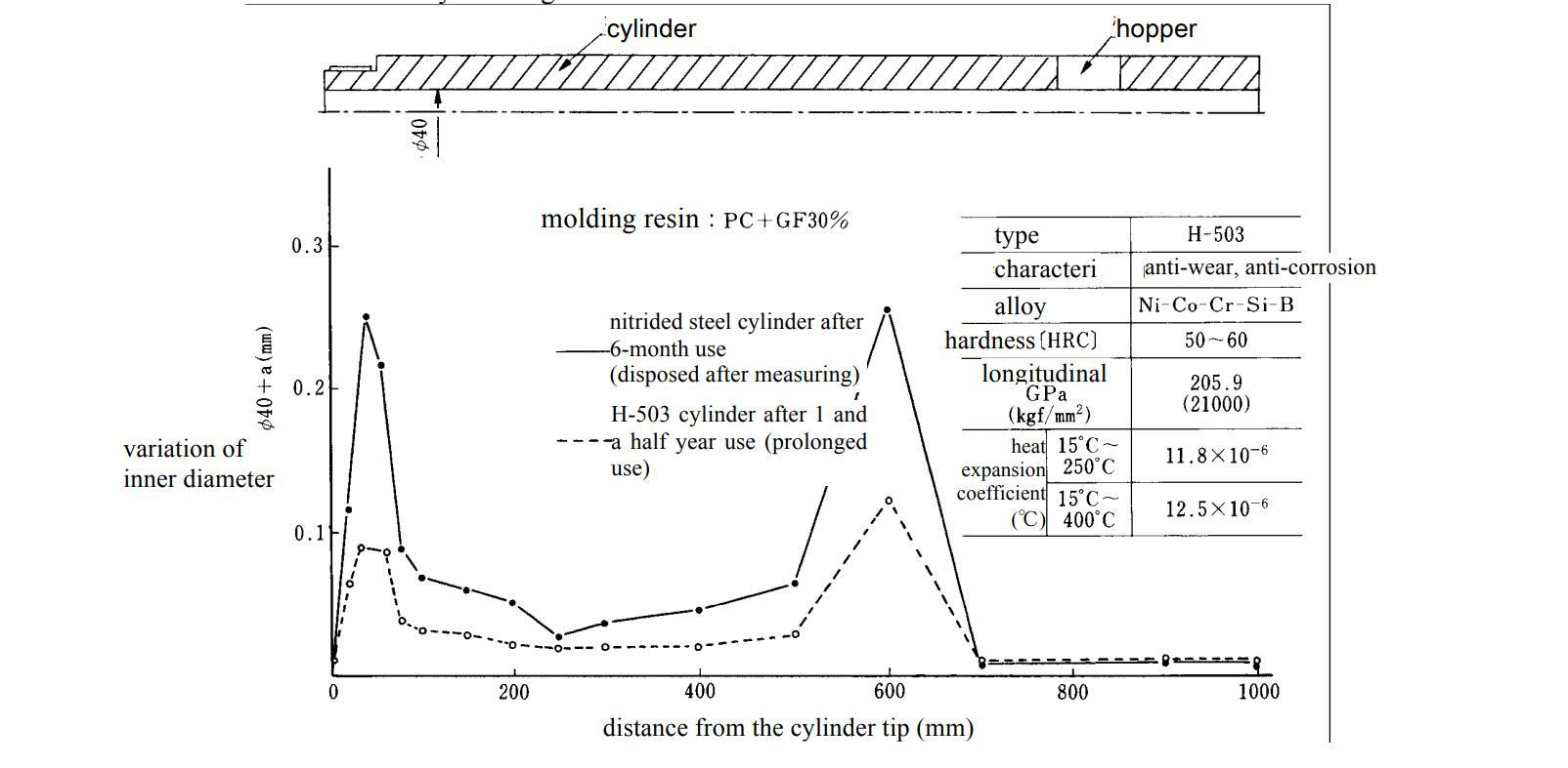
As for glass fiber reinforced PC, it is good to use the bimetal (double-structure cylinder covered the inside with another metal and centrifugal casting) to prevent the barrel abrasion. For example, the H alloy (Hitachi Metals Ltd.), N alloy (Japan Steel Works Ltd.), K alloy (Kobe Steel Ltd.) etc. are well known. Figure 1・1-3 indicates the abrasion data when molding glass fiber (30%) PC in case of using the H alloy barrel. The abrasion of the metering section vicinity where the feed section and the backflow prevention ring contact with is improved 1) .
In addition, the bimetal cylinder such as H alloy is also effective in suppressing the generation of the burn of Iupilon / NOVAREX although the burn mark and black specks due to thermal decomposition become problems in the transparent use.
1)Hitachi Metals Ltd. “H alloy” catalogue
Barrel material and abrasion data when using GF (30%) PC
3.Screw
The 3-stage type screw of the single flight is usually used. The screw design consists of the basic design based on the premises of smooth conveyance of pellet, plasticization for melting, dearation and compression, and measurement with a little unevenness.
Supply (feed section): Stroke is designed long for conveying and melting the pellet, and increasing plasticization quantity.
Compression (compression section): Return the air and water involved in the feed section to the hopper side and deaerate. In addition, a sufficiently melting mechanism is required. Because PC is a high viscosity material, the rapid compression type is unsuitable and moderating compression type with gradually increasing outside diameter is recommended.
Measurement (metering section): In order to suppress the measurement unevenness, the measurement stroke is designed long, 4D ~ 5D or more.
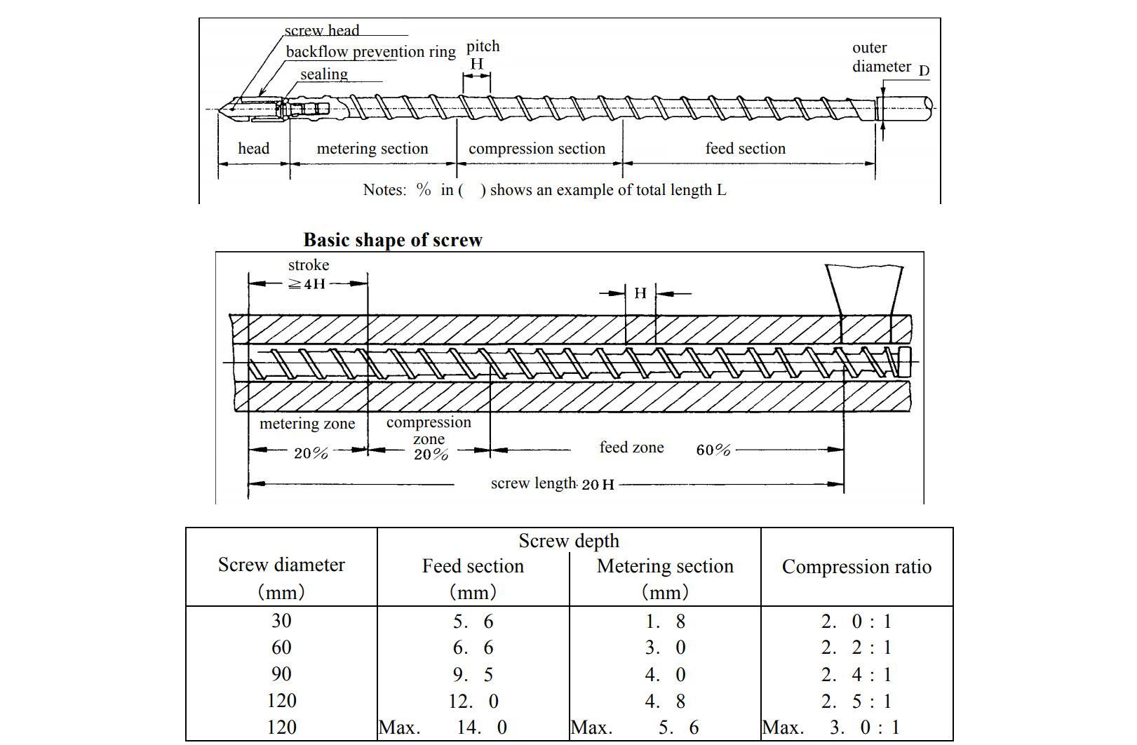
Screw pitch
H=1.0D Screw diameter more than 80mm
H=0.9D Screw diameter less than 80mm
Design of screw for PC
In the same figure, L/D is 20, the ratio of Feed (F) / Compression (C) / Metering (M) is divided into 60/20/20, pitch H
is almost equal to screw diameter D, and compression ratio C.R. of the screw is 2.0:1~2.5:1. The screw that its surface is covered with thick film hard Cr coating is good. When the glass fiber reinforced material is used, there is a problem of abrasion, but constantly preparing spare screw and regularly exchanging after recoating are recommended.
The screw that processed nitriding treatment is hard to be worn due to its high hardness. On the other hand, for transparent product and colored product (except the black) avoiding the burn, because it is easy to cause the burn in PC molding, it had better use the screw that processed with (Ni+Cr), (Co+Cr), TiC treatment at the surface though it is a little expensive.
Recently, the example which uses dulmage, sub flight, pin screw mounted at the screw head with the purpose to improve the melting and mixing and the dispersibility is observed with the precondition of not giving excessive shearing force to PC and the design without PC stagnation.
4.Backflow prevention valve, check ring
The screw head is equipped with the backflow prevention valve to maintain the effective injection pressure by preventing a part of measured resin from backflow through the ditch of the screw at the time of injection. The structure of this valve is indicated in Fig. . It can be understood that it is easy for resin stagnation with this valve structure.
Therefore, the design of the flow path without dead space by taking enough R so as not to provide the corner as much as possible is expected. In addition, as for high viscosity material such as PC, because torque is big, the fatigue failure occurs in the screw of small aperture when receiving the load by repeated rotation, the use of screw of wide aperture is recommended.
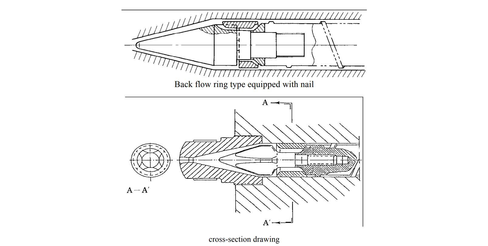
Design of Shut Off Valve
As for compound reinforced PC such as glass fiber reinforced material etc. the backflow prevention ring sometimes cracks when the load becomes large compared with the non-reinforced material. When molding without being aware of this, the uneven dimension and the deviation from tolerance in the molding of a precise part occur due to the unstable measurement. It is necessary to note that such a trouble easily occurs in case of overload and insufficient purge.
5.Nozzle
A nozzle with the structure without PC stagnation is desirable as possible. Therefore, it is necessary to avoid using the needle shut off nozzle and torpedo nozzle due to resin stagnation. The open nozzle is the best for use.
The open nozzle is easy to cause drooling, stringiness, and it is difficult to prevent them but using a long-extended nozzle and adjusting independently the temperature at two separate places of the tip and the bottom, are effective.
6.Heater
Since PC is molded at high temperature, the heater with heat capacity can be heated to about 370℃ is used, and a band heater is usually used.
When disassembling to clean the nozzle and cylinder head and when the heater is stuck with drooling resin, the heater is disconnected. It is necessary to note that it is easy to cause the burn when continuing molding without being aware of heater disconnection.