Knowledge of plastic mold
- Share
- Issue Time
- Sep 28,2020
Summary
Collection value of the most complete plastic mold knowledge
Mold profile:
"Mold is the mother of industry" this sentence we have been familiar with, the importance of mold is increasingly recognized by people, mold design and mold manufacturing technology has made great progress.
The innovation of mould processing technology, the wide application of various new mould materials, the standard and specialization of mould parts, etc.Force us in the design to be faster, more huai adapt to the development of the mold.
To improve the speed, it is required that the design section can be completed in about 3 days for the rear section: to improve the accuracy;The processing method of each part should be considered clearly in the design process, and the processing method with high precision and low processing cost should be adopted as far as possible.
The improvement of precision and speed is consistent with each other.The improvement of speed requires the improvement of precision.The improvement of precision inevitably leads to the improvement of speed.
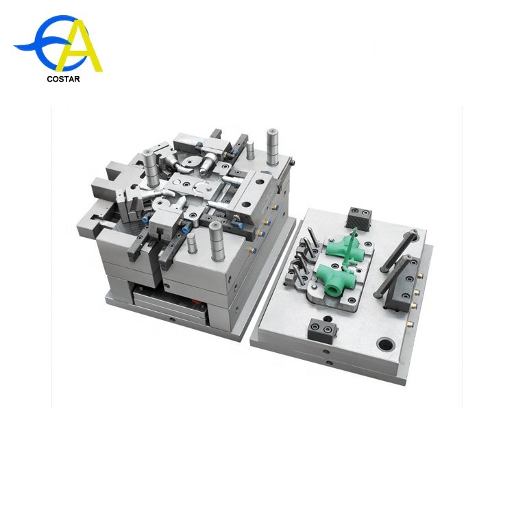
Basic structure of plastic mold:
Plastic mould can be divided into guiding system, supporting system, forming parts system, pouring system, cooling system, ejecting system and exhaust system according to the overall functional structure.
Definition: A plastic flow path in a mold from the nozzle of the injector to the cavity.It is composed of main channel, shunt channel, gate and reamer hole.
(I) Main stream:
1. Definition:
The main flow path is the part from the point where the injection machine nozzle is in contact with the mold to the point where the diverter path ends.
2. Design considerations:
(1) The end face of the main channel is usually round.
(2) In order to facilitate demoding, the main flow path is generally made with slope, but if the main flow path passes through multiple boards at the same time, it must pay attention to the slope and the size of the hole on each block.
(3) The design of the main channel size should be based on the flow characteristics of plastic materials
(4). The design of the mainstream road is mostly conical. (As shown in the figure)
A. Small-end diameter D2=D1+ (0.5~1mm)
B. Small-tip ball radius R2=R1+ (1-2mm)
(D1 and R1 are respectively the diameter of the injection outlet and the spherical radius of the injection head)
3. The gate
Because the main channel is in contact and collision with high-temperature plastics and nozzles, the main channel part of the mold is usually designed as a detachable and replaceable bushing, referred to as pouring sleeve or sprue sleeve
(1). Its main functions are:
A. Make it easy to enter the positioning hole when the mold is installed, and position the nozzle hole of the injection molding machine well on the injection molding machine, and can withstand the plastic backpressure, so as not to be pushed out of the mold.
B. As the main channel of the casting system, the plastic in the feed barrel is transferred into the mold to ensure that the material flow can reach the cavity effectively and smoothly. There should be no plastic overflow during the injection process, and the main channel condensate can be easily discharged.
(2) The structural forms are integral and split
Integral: that is, the shoulder and constitute the main part of the road made into one
Split pose: that is, the shoulder and constitute the main part of the separate production
Japanese industrial standard: JIS
China's industrial standard: SJB
(2).Shunt way:
Definition: the section between the main channel and the gate, which is the itD of molten plastic flowing into the mold cavity from the main channel, and the ITD of the casting system through the change of section area and the plastic steering, which can make the plastic get a smooth conversion.
1. Section design
A. The general design section is circular
B. The general design is u-shaped, V-shaped, trapezoidal and regular hexagon for the convenience of processing
C. The sectional shape and size of the shunt duct shall be determined according to the molding volume, wall thickness of the plastic, the shape of the plastic, the process characteristics of the plastic used, the injection rate, the length of the shunt duct and other factors.
2. The layout of the shunt duct can be divided into two forms: balanced feed and non-balanced feed.Balanced feed is to ensure that each inlet is balanced at the same time, non-balanced feed is that each inlet cannot be balanced at the same time, generally do mold flow analysis to assess.
(3). Gate
1. Definition: The gate is also called the feed gate or internal runner.It is the narrow part between the shunt duct and the plastic part, also known as the smallest part of the pouring system;
2. Function: It can accelerate the flow velocity of molten plastic transferred from the shunt to form an ideal flow pattern and sequence.It fills the mold cavity quickly, closes the mold cavity to prevent the molten material from flowing back, and facilitates the separation of the gate from the mold after molding.
3. Form of gate:
The inside of the gate
Common side gate (edge gate)
The outer gate
Fan-shaped gate: commonly used to shape a larger width of the thin sheet plastic parts
Flat slotted gate
Ear guard gate
Gap gate
General point gate
Latent gate (our company mostly use this way)
Disc ring gate
Spoke gate
Claw gate
Circular gate
4. Selection of gate location
(1) Choose the closest distance of the gate with the barrier.
(2) The size and location of the gate should be chosen to avoid spraying and peristalsis.
(3) The gate should be opened at the thickest section of the plastic parts.
(4) The choice of gate location should make the plastic flow shortest and the flow direction of the material minimum.
(5) The gate location should be selected to facilitate the discharge of gas in the mold cavity.
(6) The choice of gate location should reduce or avoid the plastic welding mark to increase the fastness of welding.
(7) The choice of gate location should prevent material flow from squeezing and deforming the cavity, stamen and insert.
(4). Cold hole
1. Structure:
The cold material hole is used to store the cold material head produced during the injection interval, to prevent the cold material from entering the cavity and affecting the quality of the plastic parts, and to make the molten material fill the cavity smoothly. The cold material hole is also called the cold material well.
2. Drawing form:
(1) Hook (working) drawing rod
(2) Ball drawing rod
3. Conical pull rod
4. Drawing hole: A.B. No ejector bar
What expertise is required for structural design
Personal opinion, for reference only!
I. Mould
For any new structural engineer, at least understand the principles of the mold (plastic mold/die-casting mold/hardware mold);
A. Mold manufacturing process (that is to say, when you draw in the future, you should consider whether the mold can be produced, how to produce the mold, whether it is convenient for mold manufacturing, and affect the service life of the mold, etc.)
B. Working principle of the mold (that is to say, when drawing, you should consider whether the mold production mode of this product will affect the normal production in the future;Such as defective injection molding, low production efficiency)
Ii. Product functions
A. First, you need to know what type of product you are dealing with.(Household appliances, communications, etc.) because the industry safety standards/testing standards are different for each type;And that's going to affect how you're going to graph it.
B. Secondly, on the premise of satisfying the product functions, simplify the drawing as much as possible, taking into account the convenience of manufacturing and maintenance of molds in the future;
3. Other relevant knowledge
A. Have relevant understanding of injection molding process;(e.g. Frequent top white/top height/trapped air/water line/air line/bubble/supporting flower/shrinkage, etc.)
B. Familiar with plastic/hardware related knowledge;The characteristics of different materials.Are different;Therefore, it is very important to select materials according to the requirements of each part in the design, which will affect the cost and reliability of the products you design in the future;
Causes of defects of injection parts and their remedies
Fill the discontent
1. Defect characteristics of injection parts
The injection molding process is incomplete because the cavity is not filled with plastic or the injection molding process lacks certain details.
2. Possible causes of problems
(1) Insufficient injection speed.
(2) Plastic shortage.
(3). There is no screw pad at the end of the trip.
(4). Variation of running time.
(5) The temperature of the charging cylinder is too low.
(6) Insufficient injection pressure.
(7) The shooting mouth is partially sealed.
(8). The heater outside the nozzle or injection cylinder cannot operate.
(9) The injection molding time is too short.
(10). Plastic is attached to the throat wall of the hopper.
(11). The capacity of the injection molding machine is too small (i.e. the injection weight or plasticizing capacity).
(12) The mold temperature is too low.
(13) The anti-rust oil of the mold was not cleaned.
(14) The check ring is damaged and the molten material has backflow.
3. Remedies
(1) Increase the injection molding speed.
(2). Check the amount of plastic in the hopper.
(3). Check whether the injection schedule is set correctly and make changes if necessary.
(4). Check whether the check valve is worn or cracked.
(5) Check whether the operation is stable.
(6). Increase the melt temperature.
(7). Increase back pressure.
(8) Increase the injection molding speed.
(9). Check the nozzle hole for foreign bodies or unplasticized plastics.
(10). Check the outer layer of all heaters with ampere meter to check whether the energy output is correct.
(11). Increase the screw forward time.
(12). Increase the cooling amount in the throat area of the hopper, or reduce the temperature in the rear area of the injection cylinder.
(13). Use a larger injection molding machine.
(14). Increase the mold temperature appropriately.
(15). Clean the anti-rust agent in the mold.
(16). Check or replace the check ring.
Size difference of injection parts
1. Defect characteristics of injection parts
The change of weight and size during the injection process exceeds the production capacity of mold, injection molding machine and plastic combination.
2. Possible causes of problems
(1) Uneven plastic in the injection cylinder.
(2) The range of injection cylinder temperature or fluctuation is too large.
(3) The capacity of injection molding machine is too small.
(4) Unstable injection pressure.
(5) The screw reset is unstable.
(6) The variation of operating time and inconsistent solution viscosity.
(7) The injection speed (flow control) is unstable.
(8). The plastic varieties that are not suitable for the mold are used.
(9). Consider the influence of mold temperature, injection pressure, speed, time and holding pressure on the product
3. Remedies
(1) Check whether there is sufficient cooling water flowing through the hopper throat to maintain the correct temperature.
(2). Check for inferior or loose thermocouple.
(3). Check whether the thermocouple used with the temperature controller is of the correct type.
(4). Check the injection volume and plasticizing capacity of the injection molding machine, and then compare it with the actual injection volume and the amount of plastic injection per hour.
(5). Check whether there is a stable molten hot material in each operation.
(6). Check the backflow preventer for leaks and replace it if necessary.
(7). Check whether the feeding setting is wrong.
(8). Ensure that the screw is stable in the return position during each operation, that is, not more than 0.4mm change.
(9). Check the inconsistency of operation time.
(10). Use back pressure.
(11). Check whether the hydraulic system operates normally and whether the oil temperature is too high or too low (25 -- 60oC).
(12). Select the type of plastic suitable for the mold (mainly from the shrinkage and mechanical strength consideration).
(13) Readjust the whole production process
Accept night mark
1. Defect characteristics of injection parts
This is usually associated with surface marks (see the "holes" section) and is caused by the plastic contracting off the mold surface.
2. Possible causes of problems
(1) The melting temperature is either too high or too low.
(2) Insufficient plastic in mold cavity.
(3) during the cooling stage, the surface in contact with the plastic will overheat.
(4) Unreasonable runner and too small gate section.
(5) Whether the mold temperature is suitable for the characteristics of plastics.
(6) Unreasonable product structure (too high, too thick, obviously different thickness).
(7) The cooling effect is not good, and the product continues to contract after demoulding.
3. Remedies
(1) Adjust the temperature of the injection cylinder.
(2). Adjust the screw speed to obtain the correct screw surface speed.
(3) Increase the injection volume.
(4). Ensure the use of correct padding materials;Increase screw forward time;Increase injection pressure;Increase injection molding speed.
(5). Check whether the check valve is properly installed, as abnormal operation may cause pressure loss.
(6). Reduce the mold surface temperature.
(7). Correct the flow passage to avoid excessive pressure loss;According to the actual needs, appropriately expand the section size.
(8) Properly control the mold temperature according to the characteristics of the plastics used and the product structure.
(9). Improve the product structure where allowed.
(10). Try to cool the product sufficiently.
Stain marks and injection marks
1. Defect characteristics of injection parts
Usually associated with the gate area: the surface is dull, sometimes with streaks.
2. Possible causes of problems
(1). Too high melting temperature.
(2) Mold filling speed is too fast.
(3) The temperature is too high.
(4). Related to the characteristics of plastics.
(5) There is cold material in the nozzle.
3. Remedies
(1). Reduce the temperature in the front two areas of the injection cylinder.
(2). Reduce injection molding speed.
(3). Reduce injection pressure.
(4). Reduce the mold temperature.
(5). Most of the parts produced by PE have injection marks, and the position of the feeding port can be modified according to the requirements of use.
(6). Avoid producing cold material as much as possible (control the nozzle temperature well).
Sprue stick
1. Defect characteristics of injection parts
The nozzle is held by the nozzle sleeve.
2. Possible causes of problems
(1) There is no correspondence between the injection muzzle and the injection nozzle.
(2) Excessive plastic stuffing in the mouth cover.
(3). The nozzle temperature is too low.
(4) The plastics are not completely solidified in the injection port, especially the injection port with large diameter.
(5) The circular arc of the injector bushing and the circular arc of the injector nozzle are improperly matched, leading to the emergence of a runner resembling "mushroom".
(6). The runner is not sufficiently inclined to pull out.
3. Remedies
(1) Re-align the injection nozzle and the injection nozzle sleeve.
(2). Reduce injection pressure.
(3). Reduce the screw forward time.
(4). Increase the nozzle temperature or heat the nozzle with an independent temperature controller.
(5). Increase the cooling time, but a better solution is to replace the original nozzle sleeve with a smaller nozzle.
(6). Correct the mating surface of the injection muzzle and the nozzle.
(7). Appropriately expand the pull out slope of the runner.
The cavity
1. Defect characteristics of injection parts
It can be easily seen in the "air trap" of a transparent molded piece but can also appear in opaque plastics.This is related to thickness and is often caused by the plastic shrinking away from the center of the injection piece.
2. Possible causes of problems
(1) The mold is not fully filled.
(2) abnormal operation of the check valve.
(3) The plastic is not thoroughly dried.
(4) Too fast pre-molding or injection.
(5) Some special materials should be produced with special equipment.
3. Remedies
(1) Increase the amount of injection.
(2). Increase injection pressure.
(3). Increase the screw forward time.
(4). Reduce the melting temperature.
(5). Reduce or increase the injection molding speed.(For example, increase the speed by 45% for non-crystalline plastics).
(6). Check whether the check valve is cracked or unable to operate.
(7) should be based on the characteristics of plastic to improve the drying conditions, let the plastic thoroughly dry.
(8) Appropriately reduce the screw rotation speed and increase the back pressure, or reduce the injection speed.
Injection piece bending
1. Defect characteristics of injection parts
The injection piece is similar in shape to the cavity but is a distorted version of the cavity shape.
2. Possible causes of problems
(1). Bending is due to excessive internal stress in the injection parts.
(2) Mould filling speed is slow.
(3) Insufficient plastic in mold cavity.
(4). Plastic temperature is too low or inconsistent.
(5) Injection parts are too hot when ejecting.
(6). The cooling is insufficient or the temperature of moving and fixed mode is inconsistent.
(7). Unreasonable structure of injection parts (such as stiffeners concentrated on one side, but far apart).
3. Remedies
(1). Reduce injection pressure.
(2). Reduce the screw forward time.
(3). Increase cycle time (especially cooling time).Immediately after ejecting from the mold (especially for thicker parts), cool the parts slowly by immersing them in warm water (38oC).
(4) Increase the injection molding speed.
(5). Increase the plastic temperature.
(6). Use cooling equipment.
(7) Properly increase the cooling time or improve the cooling conditions to ensure as much as possible the consistent mold temperature of the moving and fixed molds.
(8). If permitted according to the actual situation.
Common defects of injection molding products:
Phenomenon:
1. Insufficient injection speed.
2. Plastic shortage.
3. There is no screw pad at the end of the trip.
4. Variation of running time.
5, the temperature of the injection cylinder is too low.
6. Insufficient injection pressure.
7. The shooting mouth is partially sealed.
8. The heater outside the nozzle or injection cylinder cannot operate.
9. Injection molding time is too short.
10. Plastic is attached to the throat wall of the hopper.
11. Capacity of injection molding machine is too small (i.e. injection weight or plasticizing capacity).
12. The mold temperature is too low.
13. The anti-rust oil of the mold was not cleaned.
14, check ring damage, molten material backflow phenomenon.
Causes:
The melting temperature is either too high or too low.
2. Insufficient plastic in mold cavity.
3, the cooling stage when the surface contact plastic overheating.
4. Unreasonable runner and too small gate section.
5. Whether the mold temperature is suitable for the plastic characteristics.
6. Unreasonable product structure (too high, too thick, obviously different thickness).
7. The cooling effect is not good, and the product continues to shrink after demoulding.
Handling Measures:
1. Increase the injection speed.
2. Check the amount of plastic in the hopper.
3. Check whether the injection schedule is set correctly and make changes if necessary.
4. Check whether the check valve is worn or cracked.
5. Check whether the operation is stable.
6, increase the melt temperature.
7. Increase back pressure.
8. Increase the injection speed.
9. Check the nozzle hole for foreign bodies or unplasticized plastics.
10. Check all heater outer layers with ammeter to verify energy output is correct.
11. Increase the screw forward time.
12. Increase the throat area of the hopper or reduce the temperature of the rear area of the injection cylinder.
13. Use a larger injection molding machine.
14. Increase the mold temperature appropriately.
15. Clean the anti-rust agent in the mold.
16. Check or replace the check ring.
Product shortage:
1. Check whether there is sufficient cooling water flowing through the hopper throat to maintain the correct temperature.
2. Check for inferior or loose thermocouple.
3. Check whether the thermocouple used with the temperature controller is of the correct type.
4. Check the injection volume and plasticizing capacity of the injection molding machine, and then compare with the actual injection volume and the amount of plastic injection per hour.
5. Check whether there is a stable molten hot material in each operation.
6. Check the backflow preventer for leakage and replace it if necessary.
7. Check whether the feeding setting is wrong.
8. Ensure that the screw is stable in the return position of each operation, that is, no more than 0.4mm change.
9. Check for inconsistencies in operating hours.
10. Use back pressure.
11. Check whether the hydraulic system operates normally and whether the oil temperature is too high or too low (25-60℃).
12, choose suitable for the mold of plastic varieties (mainly from the shrinkage and mechanical strength consideration).
13. Readjusting the whole production process.
Fill dissatisfaction:
1. Adjust the temperature of the injection cylinder.
2. Adjust the screw speed to obtain the correct screw surface speed.
3. Increase the injection volume.
4. Ensure the use of correct padding materials;Increase screw forward time;Increase injection pressure;Increase injection molding speed.
5, check whether the check valve is properly installed, because abnormal operation may cause pressure loss.
6. Reduce the mold surface temperature.
7. Correct the flow passage to avoid excessive pressure loss;According to the actual needs, appropriately expand the section size.
8. Properly control the mold temperature according to the characteristics of the plastics used and the product structure.
9. Improve product mix where possible.
10. Try to cool the product sufficiently.
Size difference of injection parts
1. Uneven plastic input in the injection cylinder.
2. The range of temperature or fluctuation of the injection cylinder is too large.
3. The capacity of injection molding machine is too small.
4. Unstable injection pressure.
5. The screw reset is unstable.
6. The variation of operation time and inconsistent solution viscosity.
7. Unstable injection speed (flow control).
8, the use of the mold is not suitable for plastic varieties.
9. Consider the influence of mold temperature, injection pressure, speed, time, and holding pressure on the product.
How to simply distinguish the pros and cons of products:
Look at the appearance
1, to see whether the product is complete, deformed or not
2. Whether the color is uniform, whether there is obvious color difference, whether the color is bright and transparent
Touch products
1. Touch the surface of the product with your hands to see if it is smooth and whether there are burrs around and on the handle
2. Whether the assembly parts are appropriate and stacking is safe
3. Whether the product has been aging naturally, which is reflected in the fact that the product has become hard and brittle, while the high-quality product feels soft and tough
According to the weight
1, weigh the weight, from the raw material polymerization process and physical properties, specific gravity light means low crystallinity, high purity, less impurities
2. Products with the same structure and the same wall thickness are produced with the same raw materials and processes. In addition to the above two characteristics, the light weight is better
Principle of injection molding
I. What is injection molding?
The so-called injection molding is the plastic material in the injection molding machine barrel after external heating and the shearing heat generated by the screw rotation of the resin material into the melt, through the application of a certain pressure, the melt is injected into a certain shape of the cavity after cooling and shaping the product is injection molding.
Ii. The process of injection molding, namely the cycle of injection molding:
Mode locking
A into
Shoot glue
The holding
Melt glue + cooling
ejection
Open mould
Seat back
Three, injection molding three basic elements:
Machines - including injection molding machines, auxiliary machines.
The mould
material
Iv. Five elements of injection molding process:
1. Temperature:
A, oil temperature: for the hydraulic press, it is the heat energy generated by the hydraulic oil friction caused by the non-stop operation of the machine. It is controlled by the cooling water. Confirm that the oil temperature is about 45℃ when starting up.
B. Material temperature: that is, the barrel temperature, which should be set according to the shape and function of materials and products. If there is any document, it should be set according to the document.
C. Mold temperature: This temperature is also an important parameter, and its height has a great influence on the performance of the product. Therefore, the function and structure of the product, as well as the material and cycle, must be taken into consideration when setting.
2. Speed:
A. Speed setting of opening and closing molds. Generally speaking, setting of opening and closing molds is based on the principle of slow-fast-slow, which mainly considers machines, molds and cycles.
B. Ejection setting: it can be set according to the structure of the product. For complex structure, it is better to eject some slowly and then demoulder quickly to shorten the cycle.
C. Fire rate: it can be set according to the size and structure of the product. If the structure is complex and the wall is thin, it can be set quickly; if the wall is simple and thick, it can be set slowly.
3. Pressure:
A. Injection pressure: from low to high according to the size of the product and the thickness of the wall. Other factors should be considered during debugging.
B. Pressure holding pressure: The pressure holding pressure is mainly to ensure the product's shaping and stable size, and its setting should also be set according to the product's structure and shape.
C. Low-pressure protection pressure: this pressure mainly protects the mold to make the mold damage to the minimum.
D. Clamping force: it refers to the force required by the high pressure of clamping. Some machines can adjust clamping force, while others cannot.
4. Time:
A. Glue shooting time: the setting time must be longer than the actual time, and it can also play A role of glue shooting protection. The setting value of glue shooting time is about 0.2 seconds higher than the actual value, and the coordination with pressure, speed and temperature should be considered when setting.
B. Low-voltage protection time: under manual condition, first set the time to 2 seconds, and then add 0.02 seconds or so according to the actual time.
C. Cooling time: This time is generally set according to the size and thickness of the product, but the glue melting time should not be longer than the cooling time, so that the product can be fully set.
D. Pressure holding time: This time is the cooling time of the spout before the melt flows back under the pressure of holding pressure to ensure the size of the product after the injection, which can be set according to the size of the spout.
5. Location:
The opening and closing position of the die can be set according to the corresponding opening and closing speed. The key is to set the starting position of the low-pressure protection well, that is, the starting position of the low-pressure protection should be the point that is most likely to protect the die without affecting the cycle, and the ending position should be the position that the die is in contact with before and after the die during the slow closing.
B. Ejecting position: this position can meet the requirements of complete demodulation of the product. First, set it by increasing from small to large.
C. Glue position: calculate the material amount according to the product size and screw size, and then set the corresponding position.
D and V-p positions should be found from large to small, i.e. Short - Short method (i.e., V-P switching point).
In a word: these five elements are complementary to each other during debugging, and they must be linked to each other to set debugging.Principle of injection molding
I. What is injection molding?
The so-called injection molding is the plastic material in the injection molding machine barrel after external heating and the shearing heat generated by the screw rotation of the resin material into the melt, through the application of a certain pressure, the melt is injected into a certain shape of the cavity after cooling and shaping the product is injection molding.
Ii. The process of injection molding, namely the cycle of injection molding:
Mode locking
A into
Shoot glue
The holding
Melt glue + cooling
ejection
Open mould
Seat back
Three, injection molding three basic elements:
Machines - including injection molding machines, auxiliary machines.
The mould
material
Iv. Five elements of injection molding process:
1. Temperature:
A, oil temperature: for the hydraulic press, it is the heat energy generated by the hydraulic oil friction caused by the non-stop operation of the machine. It is controlled by the cooling water. Confirm that the oil temperature is about 45℃ when starting up.
B. Material temperature: that is, the barrel temperature, which should be set according to the shape and function of materials and products. If there is any document, it should be set according to the document.
C. Mold temperature: This temperature is also an important parameter, and its height has a great influence on the performance of the product. Therefore, the function and structure of the product, as well as the material and cycle, must be taken into consideration when setting.
2. Speed:
A. Speed setting of opening and closing molds. Generally speaking, setting of opening and closing molds is based on the principle of slow-fast-slow, which mainly considers machines, molds and cycles.
B. Ejection setting: it can be set according to the structure of the product. For complex structure, it is better to eject some slowly and then demoulder quickly to shorten the cycle.
C. Fire rate: it can be set according to the size and structure of the product. If the structure is complex and the wall is thin, it can be set quickly; if the wall is simple and thick, it can be set slowly.
3. Pressure:
A. Injection pressure: from low to high according to the size of the product and the thickness of the wall. Other factors should be considered during debugging.
B. Pressure holding pressure: The pressure holding pressure is mainly to ensure the product's shaping and stable size, and its setting should also be set according to the product's structure and shape.
C. Low-pressure protection pressure: this pressure mainly protects the mold to make the mold damage to the minimum.
D. Clamping force: it refers to the force required by the high pressure of clamping. Some machines can adjust clamping force, while others cannot.
4. Time:
A. Glue shooting time: the setting time must be longer than the actual time, and it can also play A role of glue shooting protection. The setting value of glue shooting time is about 0.2 seconds higher than the actual value, and the coordination with pressure, speed and temperature should be considered when setting.
B. Low-voltage protection time: under manual condition, first set the time to 2 seconds, and then add 0.02 seconds or so according to the actual time.
C. Cooling time: This time is generally set according to the size and thickness of the product, but the glue melting time should not be longer than the cooling time, so that the product can be fully set.
D. Pressure holding time: This time is the cooling time of the spout before the melt flows back under the pressure of holding pressure to ensure the size of the product after the injection, which can be set according to the size of the spout.
5. Location:
The opening and closing position of the die can be set according to the corresponding opening and closing speed. The key is to set the starting position of the low-pressure protection well, that is, the starting position of the low-pressure protection should be the point that is most likely to protect the die without affecting the cycle, and the ending position should be the position that the die is in contact with before and after the die during the slow closing.
B. Ejecting position: this position can meet the requirements of complete demodulation of the product. First, set it by increasing from small to large.
C. Glue position: calculate the material amount according to the product size and screw size, and then set the corresponding position.
D and V-p positions should be found from large to small, i.e. Short - Short method (i.e., V-P switching point).
In a word: these five elements are complementary to each other during debugging, and they must be linked to each other to set debugging.