Basics of Injection Molding Design
- Share
- Issue Time
- Nov 4,2020
Summary
Designing plastic parts is a complex task that involves many factors and can meet a range of application requirements."How is the part used?""How does it fit into the rest of the assembly?""What kind of load does it carry?"In addition to functional and structural problems, machining problems also play an important role in the design of injection molded plastic parts.
Application
Plastic injection molding is the preferred process for manufacturing plastic parts.Injection molding can be used to make many things, such as electronic casings, containers, bottle caps, car interiors, combs, and most other plastic products available today.Because multiple injection molds can be used to produce multiple parts per cycle, they are ideal for producing large Numbers of plastic parts.Some advantages of injection molding are high tolerance accuracy, high repeatability, wide range of material selection, low labor cost, small waste loss and almost no need for finishing parts after forming.Some of the drawbacks of this process are the expensive upfront tooling investment and process constraints.
Best polymer for injection molding
Most polymers can be used, including all thermoplastics and some elastomers.Tens of thousands of different materials can be used for injection molding.The availability of materials mixed with alloys or previously developed mixtures of materials means that product designers can choose from a wide range of materials to find materials with the right properties.Select materials according to the strength and function required for the final part;And each material has different molding parameters that must be considered.Common polymers such as nylon, polyethylene, and polystyrene are thermoplastic.
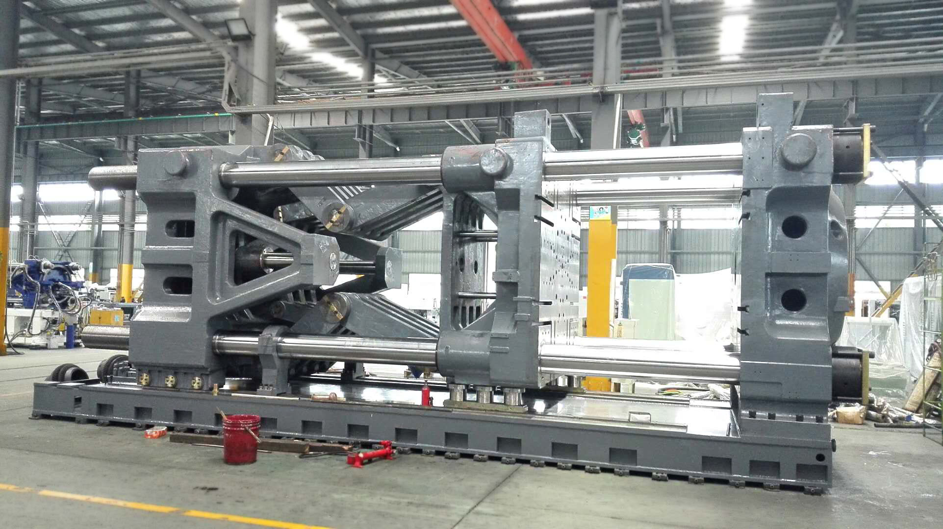
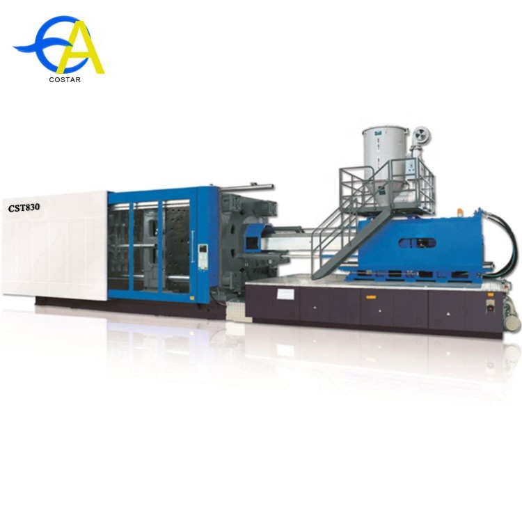
Injection molding equipment
Injection molding machine:
An injection molding machine, also known as a press machine, consists of a hopper, an injection or screw plunger, and a heating unit.The mould is clamped onto the pressing plate of the moulding machine and then the plastic is injected into the mould through the sprue.The press is graded by tonnage, which is the calculated value of the clamping force that can be exerted by the machine.This force keeps the mold closed during injection.Tonnage ranges from less than 5 to 6,000 tons, although higher tonnage presses are rarely used.The total clamping force required is determined by the projected area of the molded custom part.For each square inch of projected area, the projected area is multiplied by 2 to 8 tons of clamping force.As a rule of thumb, most products can use 4 or 5 tons/inch.If the plastic material is very hard, more injection pressure is required to fill the mold, so more clamping tonnage is required to keep the mold closed.The force required may also be determined by the materials used and the dimensions of the parts having larger plastic parts and requiring higher clamping forces.
The subgate is the only auto-trimming gate on the list.Automatic trim of the gate will be required to have a push.Secondary gates are very common, and there are many variants, such as banana gates, tunnel gates and smiley face gates.The subgate allows you to move away from the parting line gate, providing greater flexibility to place the gate in the best position on the part.The gate leaves a stitch - sized scar on the part.
The hot search door is the most common of all heat channel doors.The hot gate gate is usually located at the top of the part, rather than on the parting line, and is ideal for circular or conical shapes that require uniform flow.The gate leaves a small raised patch on the surface of the part.Hot point gate is only used with hot runner forming system.This means that, unlike a cold runner system, the plastic is sprayed through a heated nozzle into the mould, where it is then cooled to the appropriate thickness and shape.
The direct or nozzle is a manual trim gate used for those large cylindrical parts requiring symmetrical filling using a single cavity mold.Direct gates are the easiest to design with low cost and maintenance requirements.Direct gate parts usually have low stress and high strength.The gate leaves a large scar on the part at the contact point.
Gate location
To avoid problems with your gate location, here are some guidelines for choosing the right gate location:
The gate is placed on the heaviest cross section to allow the parts to be packed and to minimize voids and subsidence.
By placing the gate away from the core and pin, obstacles in the flow path are minimized.
Ensure that the stress from the sprue is located in an area that does not interfere with the function or aesthetics of the parts.
If high shrinkage grade plastics are used, the parts may contract near the gate when the die pressure at the gate is high, resulting in "gate fold".
Ensure easy manual or automatic degumming.
The gate should be as far as possible to reduce the length of the flow path, so as not to produce flow marks.
In some cases, it may be necessary to add a second gate to fill the parts properly.
If the thin-walled parts have filling problems, increase the runner or adjust the wall thickness to correct the flow.
The size and shape of the gate will vary depending on the type of plastic to be moulded and the size of the part.Large parts will require a larger gate to provide greater resin flow, thus reducing the molding time.Small gates have a better appearance, but take longer to form, or may require higher pressure to fill properly.
Wall thickness
The injection molded parts are cooled from the manufacturing temperature prior to demoulding from the mold in order to retain their shape during demoulding.During the part cooling process, changes in pressure, velocity and plastic viscosity should be minimized to avoid defects.In the meantime, few aspects are more important than wall thickness.This feature can have a significant impact on the cost, production speed, and quality of the final part.
Appropriate wall thickness:
Choosing the right wall thickness for your parts can have a huge impact on manufacturing costs and production speed.Although there is no limit to wall thickness, the general goal is to choose as thin a wall as possible.Thinner walls use less material, resulting in lower costs and reduced cooling times, resulting in shorter cycle times.
The minimum wall thickness that can be used depends on the size and geometry of the part, the structural requirements, and the flow performance of the resin.The wall thickness of injection molded parts is usually 2mm-4mm (0.080 "-0.160").Thin-walled injection molding can produce walls as thin as 0.5mm (0.020 ").The following figure shows the recommended wall thickness for common injection molding resins.
Uniform wall thickness:
The thick parts take longer to cool than the thin ones.In the cooling process, if the wall thickness is inconsistent, the thinner wall will cool first, but the thick wall will still solidify.As the thicker part cools, it contracts around the thinner part, which is already firm.This can result in warping, twisting, or cracking where the two parts meet.To avoid this problem, try to design perfectly uniform walls throughout the part.If uniform walls are not possible, the variation in thickness should be as gentle as possible.The wall thickness change of high - modulus shrink plastics should not exceed 10%.The thickness transition should be gradual, on the order of 3 to 1.This gradual transition avoids stress concentration and sudden cooling differences.
Sink mark
When hot melt flows into an injection mold, the thicker part does not cool as quickly as the rest because the thicker material is insulated by the outer surface of the cooler plastic.As the core cools, it contracts at a different rate than an already-cooled shell.This difference in cooling rate can cause the thick-walled parts to pull inward and create dents in the outer surface of the parts, or worse, the parts to warp completely.In addition to being unattractive, the markings indicate additional stresses built into the parts.Other less obvious areas where subsidence occurs include ribs, lugs and corners.These are often overlooked because neither the features nor the parts themselves are too thick.But the intersection of the two can be a problem.
One way to avoid sinking is to remove the solid portion of the part to reduce the thicker area.If you need the strength of a solid part, try using a rib pattern with cross shading lines inside the hollow area to increase strength and avoid sinking.In principle, ensure that all lugs and positioning/supporting ribs are not more than 60% of the nominal wall thickness.In addition, textures can be used to hide smaller indentation.
Texture
Texturing is the process of applying a pattern to the surface of a die.This process provides the flexibility to create the final appearance of the part.Texturing is an integral part of product development and should be considered during the design process to achieve the desired results.Texture can also be a functional part of a design.Incorrect parts may be covered by the correct texture.Are parts designed for regular handling?Textures can be used to hide fingerprints and improve end user grip.Texture can also be used to reduce wear of parts caused by friction.
A variety of textures can be used for injection parts, such as:
Natural/exotic
Inferior smooth finish
Multigloss pattern
merge
graphics
Leather grain/leather
Wood grain, SLATE and cobblestone
Geometry and flax
Layered textures create a new look
An image or logo contained in a pattern
When applying textures to parts, CAD engineering drawings must be adjusted to accommodate the surface changes.If the texture is on a surface perpendicular or angled to the mold opening, there is no need to change the draft depth.However, if the texture is on a surface parallel to the die opening, the die depth must be increased to prevent scratches and scratches during the part's ejection.Different textures have different effects on the molded parts.The rule of thumb when designing textures is that each 0.001 inch of texture should have a 1.5 degree depth of undie.
Parting line
The parting line is the parting line at the intersection of the two halves of the mold.The line actually represents the part "plane" through the part.While the plane may be a simple flat surface on a simple part, it is usually a complex form that tracks the periphery of the part around the various features that make up the "contour" of the part's exterior.The parting line may also appear at any point where two parts of the mold meet.This may include side operated pins, tool inserts and globe valves.Parting lines are unavoidable.Every part has them.When designing parts, keep in mind that the melt will always flow to the parting line, as this is where the discharged air is most likely to escape or "exhaust".
Common casting defects
Injection molding is a complex technology that can cause production problems.They may be caused by defects in the mold, or they may be caused by parts processing (forming)
Keep these factors in mind when designing molded parts, and remember that it is easier to avoid problems in the first place than to change the design in the first place.
| Molding Defects | Alternative Name | Descriptions | Causes |
|---|---|---|---|
| Blister | Blistering | Raised or layered zone on surface of the Plastic part | Tool or material is too hot, often caused by a lack of cooling around the tool or a faulty heater |
| Burn marks | Air Burn/Gas Burn | Black or brown burnt areas on the plastic part located at furthest points from gate | Tool lacks venting, injection speed is too high |
| Color streaks (US) | Localized change of color | Plastic material and colorant isn't mixing properly, or the material has run out and it's starting to come through as natural only | |
| Delamination | Thin mica like layers formed in part wall | Contamination of the material e.g. PP mixed with ABS, very dangerous if the part is being used for a safety critical application as the material has very little strength when delaminated as the materials cannot bond | |
| Flash | Burrs | Excess material in thin layer exceeding normal part geometry | Tool damage, too much injection speed/material injected, clamping force too low. Can also be caused by dirt and contaminants around tooling surfaces. |
| Embedded contaminates | Embedded particulates | Foreign particle (burnt material or other) embedded in the part | Particles on the tool surface, contaminated material or foreign debris in the barrel, or too much shear heat burning the material prior to injection |
| Flow marks | Flow lines | Directionally "off tone" wavy lines or patterns | Injection speeds too slow (the plastic has cooled down too much during injection, injection speeds must be set as fast as you can get away with at all times) |
Jetting | Deformed part by turbulent flow of material | Poor tool design, gate position or runner. Injection speed set too high. | |
| Polymer degradation | polymer breakdown from oxidation, etc. | Excess water in the granules, excessive temperatures in barrel | |
| Sink marks | Localized depression (In thicker zones) | Holding time/pressure too low, cooling time too short, with sprueless hot runners this can also be caused by the gate temperature being set too high | |
| Short shot | Non-Fill/Short Mold | Partial part | Lack of material, injection speed or pressure too low |
| Splay marks | Splash Mark/Silver Streaks | Circular pattern around gate caused by hot gas | Moisture in the material, usually when resins are dried improperly |
| Stringiness | Stringing | String like remain from previous shot transfer in new shot | Nozzle temperature too high. Gate hasn't frozen off |
| Voids | Empty space within part (Air pocket) | Lack of holding pressure (holding pressure is used to pack out the part during the holding time). Also mold may be out of registration (when the two halves don't center properly and part walls are not the same thickness). | |
Weld line | Knit Line/Meld Line | Discolored line where two flow fronts meet | Mold/material temperatures set too low (the material is cold when they meet, so they don't bond) |
| Warping | Twisting Part | Distorted part | Cooling is too short, material is too hot, lack of cooling around the tool, incorrect water temperatures (the parts bow inwards towards the hot side of the tool) |